What is High-Speed Machining
High-speed machining, or HSM, has many definitions among the CNC machinist community, but in general it communicates a modern style of machining that aims to increase productivity and extend tool life. This machining style incorporates a handful of core techniques, which we’ll cover in this post. The recipe that most machinists rely on includes high spindle speeds and feed rates, high depths of cut (DOC), low widths of cut (WOC) or stepover, and toolpaths that produce constant tool engagement.
Why HSM?
For those new to CNC, one of the challenges a machinist faces is keeping an end mill cool during a machining operation and avoiding any tool welding with the chips coming off of the workpiece. Regardless of how you classify HSM, this chart cuts to the heart of why this style of machining can be beneficial. It’s somewhat counterintuitive to what you might expect, but the cutting temperatures actually decrease at a certain point as you increase the cutting speed on a CNC machine. And moving faster means increasing overall machine productivity while still not sacrificing tool life.
What’s in an HSM Recipe?
Let’s break down what makes up a typical HSM recipe and define a few terms and equations. We’ll try our best to avoid a full-on math class here.
Surface Feet Per Minute (SFM): A description of how far a spot on the rotating cutting tool will travel in a minute relative to the workpiece.
SFM also relates to the machinability of the material: Harder materials like titanium have a lower SFM than softer materials like aluminum. These numbers usually have a large range as well, but HSM applications for aluminum typically have an SFM that begins around 1,000 and goes up from there. Okay, so how does this relate to spindle speed, tool diameter, and the other ingredients that make up our HSM recipe?
SFM = RPM * .262 * Tool diameter
RPM = SFM * 3.82 / Tool diameter
These two equations highlight an early rule of thumb that you learn in CNC milling: Smaller tools call for higher RPMs and larger tools require lower RPMs. Now that we’ve used this SFM number to understand how to calculate a required spindle speed, let’s look at how our tool size plays into feed rates.
Feed Rate (IPM): How fast the cutting tool is moving through the workpiece in the X or Y direction in a given minute, expressed in inches or millimeters.
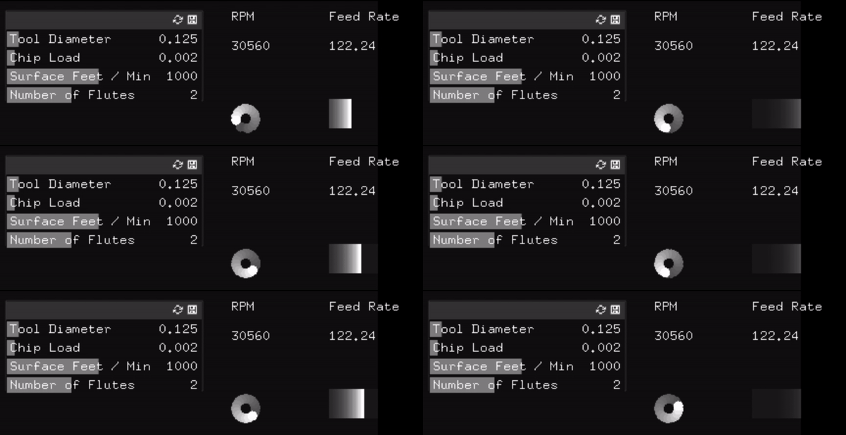
Feed Rate = Revolutions per min * Chip load per tooth * Number of flutes
One of the other rules of thumb you learn early on in machining is that the relationship between feed rate and spindle speed is linear: The faster your spindle can rotate, the faster you can feed the end mill through the workpiece. Increasing the number of flutes on a tool also allows a machinist to increase feed rates and therefore production speed.
There’s one catch, however: Both the number of flutes and the amount of material being removed by each flute in one rotation or chip per tooth (measured in “inches per tooth” or IPT) can cause more stress on the tool and machine, as well as sacrifice the surface finish of the part. Taking a “lighter” cut is one way that HSM addresses this.
Small But Mighty
While traditional machining may call for a large tool to “hog” away material, the HSM approach is more quick and nimble, or as we say at Bantam Tools, small but mighty. With the HSM approach of taking a lighter cut in the material while maintaining the high spindle speeds and feed rates, some productivity, or material removal rate, is sacrificed, but overall, a smaller tool moving faster in this fashion is more efficient than a large tool moving slowly.
Depth of Cut & Width of Cut
Like most ingredients in this speeds and feeds recipe, HSM also turns the typical depth of cut and width of cut on its head. Traditional machining strategies pair a low depth of cut and high width of cut with a conservative feed rate. The HSM approach pairs a high depth of cut—utilizing as much of the flute length as possible—and a low width of cut (typically 5%–20% of the cutter diameter) with a high feed rate, as we learned above.
This smaller width of cut means that with each cutting revolution, the tool also has more time disengaged with the workpiece and therefore more time to stay cool.
Constant Engagement Toolpaths
The last piece of the HSM recipe takes advantage of constant engagement toolpaths. If we look at a slotting operation, where an end mill is fed in a straight line through the workpiece, the tool is engaged in 180° of the material as it clears material in front, leaving a slot behind.
Using this same slotting operation but with an HSM strategy, the tool will actually peel away material in small arcs, as opposed to moving in a straight line. This is called trochoidal slotting. With this approach much less of the tool is engaged in the workpiece and the forces are greatly reduced, again allowing for faster cutting than compared to a larger tool moving slower through the workpiece.
This concept more broadly applies to the way in which hard 90° turns in toolpaths are avoided in HSM. If you’re a Fusion 360 user the adaptive toolpaths that are generated are designed to avoid sharp corners and keep the tool moving in a way that optimizes for speed and overall cutting efficiency.
Recipe for Efficiency
Putting these techniques together on our Bantam Tools Desktop PCB Milling Machine, we were able to increase the material removal rate by 375% when compared to our more traditional machining strategies. We’re excited to keep exploring the limits of HSM in the desktop CNC environment.
For the latest high-speed machining projects, be sure to follow us on Instagram, Twitter, and Facebook.


