Integrating CNC Machining into Your STEM Program
We recently caught up with Steve Temple, who runs the Academy of Engineering and Tech program at San Rafael High School. The two-year STEM program has been running for the past 16 years and is focused on engineering, physics, and computer science. Students take two courses each year and are introduced to a variety of digital fabrication tools, including our small but mighty Bantam Tools Desktop PCB Milling Machine, for their electronics-based projects.
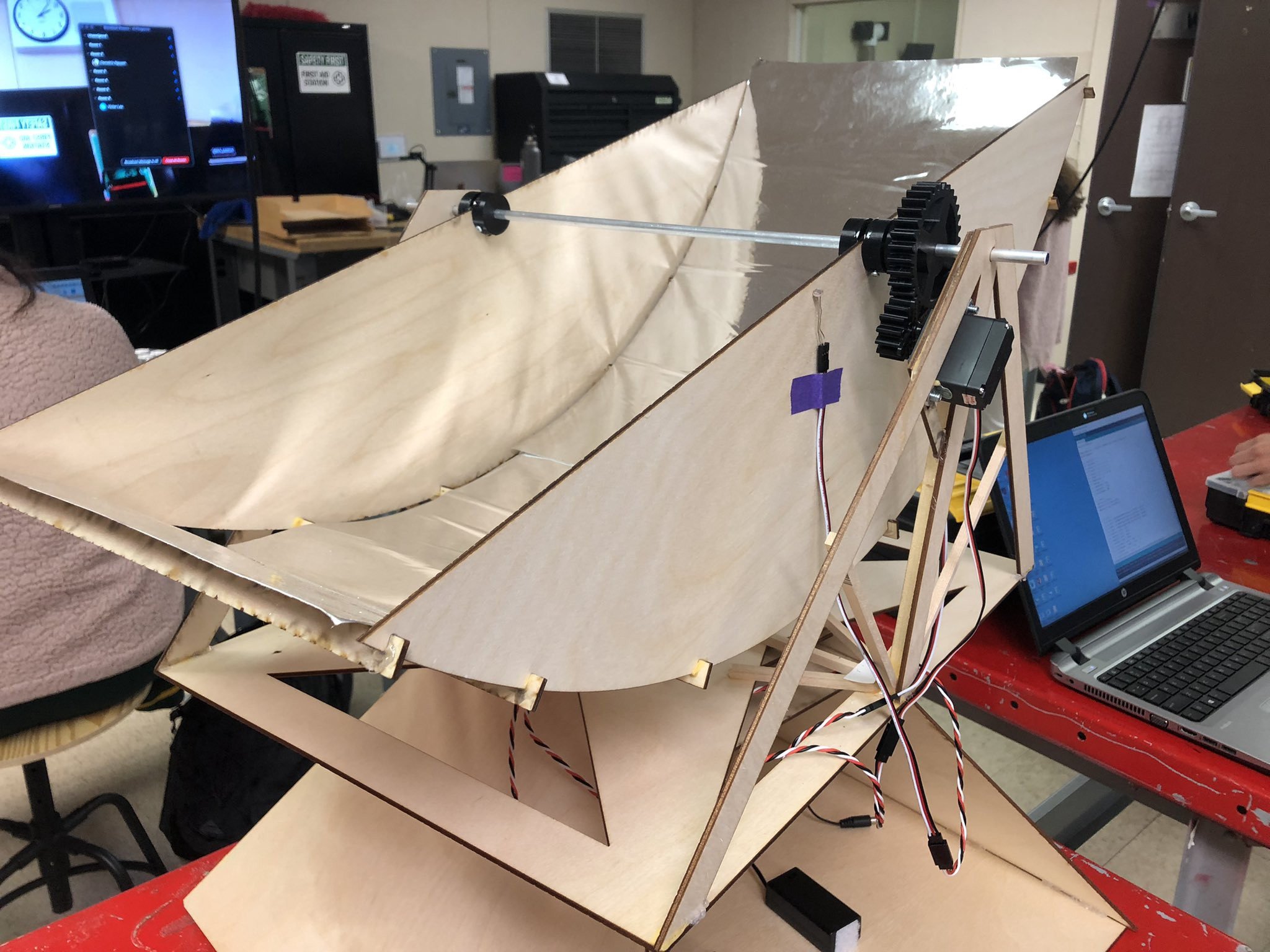
Steve shared a number of the most recent projects his students worked on during the academic school year, including a solar-powered hot dog cooker and Arudino maze bots. Naturally, we wanted to learn more about how this innovative program uses our mill to help students build their CNC machining skills.
What inspired the solar-powered hot dog cooker? What about the Arduino Maze Bots?
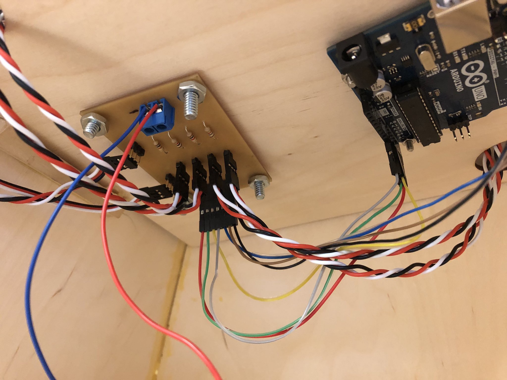
The hot dog cooker project is actually a solar tracker that uses photocells connected to an Arduino to sense light intensity differences. The Arduino controls two servos that then move to minimize the light differences. The cookers are parabolic reflectors that were designed to concentrate the sun on the hot dogs.
We wanted a project that would be fun for the students, but also one that presented a challenge where they needed to think about the mechanical components, the sensor input data, the electrical components and how to integrate these into a functional apparatus. This was meant to be an intro project before building the maze robot. It turned out to be quite a bit more challenging than we expected, but it was still great preparation for the maze robots.
We’ve been doing the maze robot project for a number of years now. We first did a “battle bot” competition but realized that the students had figured out a winning formula and so the robots all started to be very similar in design.
Now that we’ve challenged them to navigate a maze, the robots that the students produced used very different designs and strategies, which was much more interesting for the students — and those observing the competition.
Could you give us more insight into the process for making these projects? Are these created in teams? What does the workflow look like?
All the projects are team-based. We typically use only two-person teams, but this year we did three-person teams for the maze bots, which actually worked out really well. These types of mechatronics projects tend to lend themselves well to identifying three areas of focus: mechanical, electrical, and control, with a fourth focus that is shared — integration.
The teams decided who would be in charge of what area (or “system,” as we called them) and then each was in charge of communicating to the others. We follow a process for every project:
Ideation: This involves paper and pencil sketches and research.
Design: This involves CAD using Fusion 360.
Fabrication: We have 3D printers, a laser cutter, various power and hand tools, etc.
Integration and testing: This is where students build the design, see if it works, and iterate as needed.
All phases of the project involve instructor or peer critique and approval in order to move to the next phase. There are deliverables in each phase, and the students use Trello to manage their project and keep themselves organized.
What’s one of you and your students’ favorite features of the Bantam Tools Desktop PCB Milling Machine?
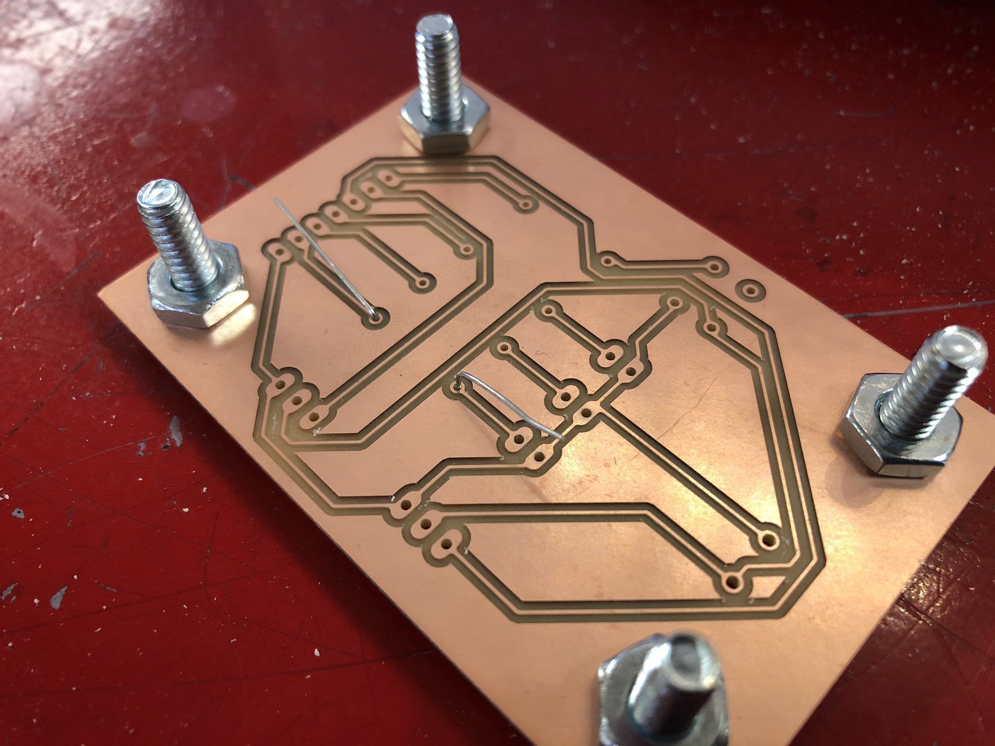
The Bantam Tools Desktop PCB Milling Machine is so easy to use with Fusion 360, especially now with the EAGLE integration. As an instructor, I like how fast and easy it is to set up an FR-1 blank, get it cut, and hand it off to the students for soldering. We used to just have the students build their circuits on a breadboard (which we still do so that they can be sure their design works), but now that we’ve moved to using PCB’s in our projects, and it’s provided us with a few advantages.
From the student’s perspective, breadboards are bulkier, the wires tend to fall out, and they run out of space on the smaller ones very quickly. From my perspective, I can now introduce them to the world of PCB design software (Fusion 360), soldering, and testing. This really makes the students feel like they’re doing electronics like the pros.
What has the PCB mill enabled you to do that you previously couldn’t?
It gives the students some exposure to new skills and tools. This also allows me to introduce the world of CNC machining to them. They get to see, on a small scale, how a design on a computer screen can become a physical reality. It really helps them begin to see the connection to other CNC operations and how milling in particular can be used to create physical 3D parts. Although we currently don’t do any CNC milling beyond our PCB-based projects, it’s inspired us to bring in more CNC fabrication for small parts, and we’re planning on incorporating some simple CAM fabrication next year!
How does the PCB mill fit in with the other digital fabrication tools you have in your makerspace?
We’ve used 3D printing, as well as laser cutting, since the inception of our program. The Desktop PCB Milling Machine was a tool we added later on. Although there are some obvious strengths to 3D printing, it’s an incredibly time-consuming process and it’s a black box for the students. They just send the file, and I typically prepare the printing. Laser cutting is great, but it’s limited in terms of materials, as well as design. Together, with some fabrication being done manually using various other tools in the shop, like a bandsaw or other power tools, we can fabricate the mechanical components for the student projects.
The Desktop PCB Milling Machine allows us to use advanced fabrication for the electrical system (with some manual assembly using a soldering iron, of course). We intend to bring in some additional uses for CNC milling so that students can have a full perspective of both additive and subtractive manufacturing.
I personally love subtractive with softer materials because we can create many of the same 3D parts that we created on a 3D printer in a fraction of the time, and the students get to learn an introduction to the different strategies used by machinists, which they find fascinating. Although this might not seem like an important point, students love watching the Desktop PCB Milling Machine do its thing.
What are three tips you would offer educators looking to incorporate a Bantam Tools CNC machine into their classroom or makerspace?
Overall, I’d say that the machine is really easy to use, but it’s important to understand that just like other fabrication tools, it has its own set of things you have to get used to and manage. Cutting PCB boards is quite easy, but designing a PCB board is a bit tricky, as it requires understanding settings in the software to make your paths the correct size. Dialing in these settings takes a bit of trial and error, but once you have them, you can really work efficiently. We were able to get all our robot teams to design their PCBs one day, and then cut them out the next.
Similarly, soldering circuit boards can be challenging for students, so I suggest a mini project where they get to practice before jumping into more complex projects. If you’re doing other CNC machining, it’s good to go with softer materials first so you can move through student projects quickly. And, once again, stick to some simple CAM setups.
There are great resources out there. Fusion 360’s CAM setup tools are amazing and work flawlessly with the Bantam Tools Desktop PCB Milling Machine.
About San Rafael High School’s Program
The Academy of Engineering and Tech program at San Rafael High School is a two-year STEM program has been running for the past 16 years and is focused on engineering, physics, and computer science.
Follow Bantam Tools on Instagram, Facebook, Twitter, and be sure to subscribe to the Bantam Tools mailing list to receive more content like this.


